
Water recycling plant uses reverse osmosis to further treat wastewater after the ultra filtration process reverse osmosis membranes are constructed from a membrane flat sheet. It is comprised of three layers:-
• A polyester fabric support base
• A micro-porous poly cell phone layer and
• A point two micron thick polyamide barrier layer
The polycellphone layer strengthens the very thin barrier layer it is the barrier layer that removes nutrients chemicals bacteria and viruses from the water. The membrane flat sheet is combined with a sheet of feed channel spacer this provides turbulence and creates space between the membrane sheets for the feed water . A sheet of permeate spacer is added to the membrane sheets and feed channel spacer this enables the final recycled water product or permeate to flow evenly across the entire membrane surface even under high pressure. The back of the membrane is completely sealed to the edges of the permeate spacer. The membrane sheets are glued along each of the three exposed sides and rolled around the core tube feed water is forced through the feed channel spacer and into the barrier layer of the membrane water passes through the membrane surface into the permeate channel. It flows in a spiral direction and collects in the core tube, this water is the final recycled water product or permeate . There are seven spiral wound elements loaded in one pressure vessel, once the end adapter is connected to the last element and the pressure vessel is sealed , feed water can be introduced.
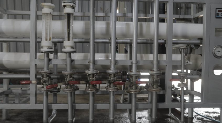
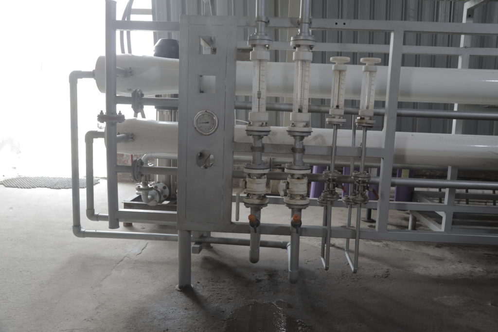
Feed water is pumped at high pressure into the vessel, as it travels , small molecules like water pass through the membrane, while larger particles such as salt bacteria and viruses do not. The final recycled water product is collected from the end of the elements, the concentrate or reject from that vessel flows to another stage producing more recycled water.
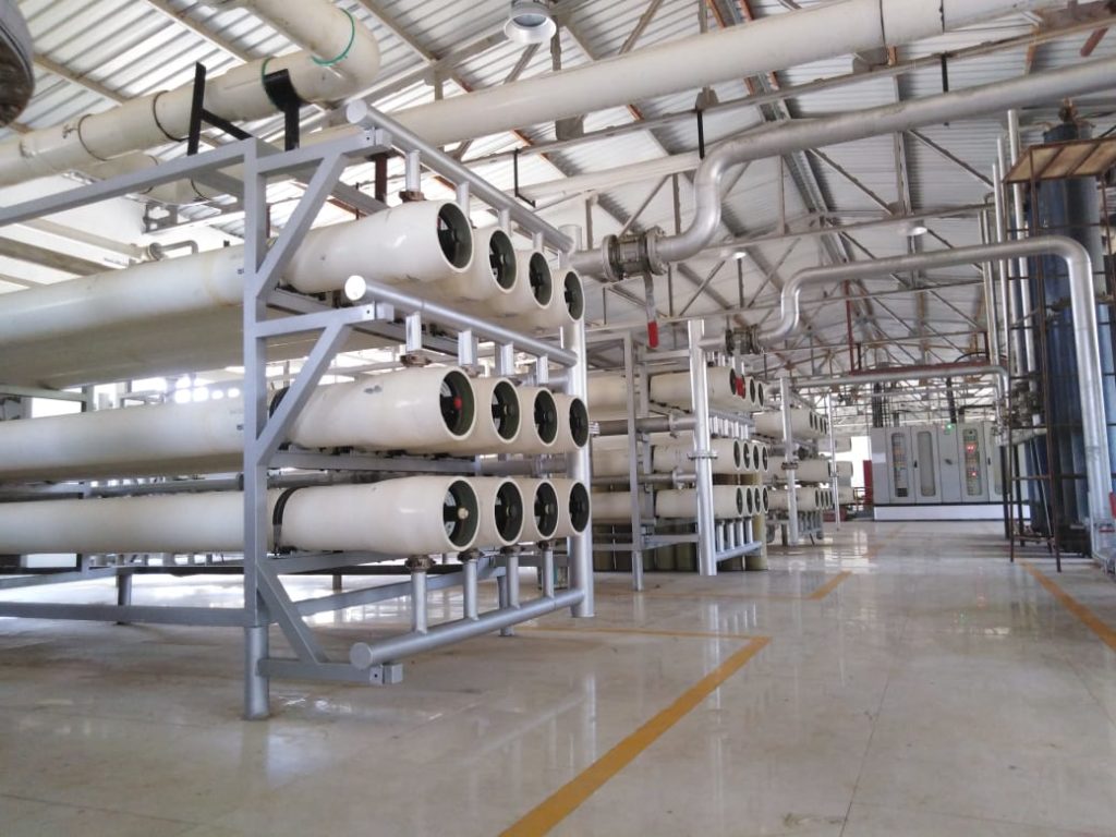
A common pressure vessel has a fiberglass shell and contains six spiral-wound RO elements spiral-wound elements can range in size from 2 to 12inches in diameter and twelve to over 40 inches in length a very common size that is used for industrial water purification is an element which is eight inches in diameter by 40 inches in length when six elements are placed in a pressure vessel male couplers connect the product tube in each element to the product tube of the next element this interconnection allows permeate from all elements to exit the pressure vessel in either direction typically one end of the pressure vessels product tube is capped , while the other is open to allow product water to exit.
The couplers generally have double O rings on each side, these o-rings on the couplers are used to prevent higher pressure feed water from passing into the product tube thus contaminating the product water . Each element has a brine seal placed in the groove located on the outside of the anti telescoping cap it is critical that this brine seal always be placed on the feed water inlet side of the element and that, the seal open in the direction of the feed water this seal prevents feed water from going around the element rather than through it both the inlet and outlet side of the pressure vessel used an adapter on the inlet side of the pressure vessels . An adapter with a rings fits onto the product tube of the first element the permeate port adapter fits onto the main adapter a sealing plate with an o-ring and the bearing plate fit over the permeate port adapter a locking ring set that fits into a slot on the inside of the pressure vessel is used to hold these plates in place and the securing ring and screws are used to hold the locking ring set in place the feed water port fits through the ceiling plate tor each the cavity between the ceiling plate and the first element a port nut and permeate port end plug complete the inlet sight assembly the outlet side of the pressure vessel is identical in construction with the exception of a thrust collar the thrust collar is used to protect against the tremendous pressure which otherwise would be totally loaded on the end adapter to appreciate the pressure that the thrust collar must endure consider a pressure vessel where each of the six elements has a differential feed water pressure of 10 psi the resulting 60 psi of differential would be multiplied by the elements surface area of approximately 50 square inches to obtain the total force exerted which would be approximately 3000 pounds at the end adaptor.
Now all of this ,may seem a little too technical at first and it is, but this is what helps us achieve clean drinking safe water after recycling, what was once wastewater. The ever-evolving technologies have helped us over the years, to be able to achieve this, which was once a dream, but a necessity today.
Hyper strives to work harder each day, assuring our best services at all times.